
現貨供應最新開發模組
LoNet Mini GSM/GPRS Breakout


- 四頻 850/900/1800/1900MHz
- GPRS multi-slot class12 最高上下傳 85.6kbps
- GPRS mobile station class B,標準 SIM 卡
- AT Command (3GPP TS 27.007, 27.005 and SIMCOM)
- 3.4V ~ 4.4V 供電、支援 RTC 及 A-GPS
- 3.0V 至 5.0V 邏輯準位,休眠時僅耗電 1mA
- 精緻小巧 23mm x 35mm x 5.6mm, 7g
代號
lonet-mini-gsmgprs
SKU 即原廠標號
109990071
原廠連結:http://www.seeedstudio.com/wiki/LoNet_-_GSM/GPRS_Breakout
Overview
This is not the replacement for the LoNet - Mini GSM/GPRS/GPS Breakout, but a simplified version without GPS function. It is based on SIM800L module, supports quad-band GSM/GPRS network, available for GPRS and SMS message data remote transmission.
The board features compact size and low current consumption. The size is only two times as large as a coin. With power saving technique, the current consumption is as low as 1mA in sleep mode. It communicates with microcontroller via UART port, supports command including 3GPP TS 27.007, 27.005 and SIMCOM enhanced AT Commands. It also has built-in level translation, so it can work with microcontrollor of higher voltage than 2.8V default. Beside, the board also supports A-GPS technique which is called mobile positioning and gets position by mobile network. This features make it can also be a tracker module.
This board is specially designed for project in a small box and powered by 3.7 li-po battery. If you want a Arduino shield, we are suggesting you pick up the SeeedStduio GPRS Shield.
Features
- Quad-band 850/900/1800/1900MHz
- GPRS multi-slot class12 connectivity: max. 85.6kbps(down-load/up-load)
- GPRS mobile station class B
- Controlled by AT Command (3GPP TS 27.007, 27.005 and SIMCOM enhanced AT Commands)
- Supports Real Time Clock
- Supply voltage range 3.4V ~ 4.4V
- Supports A-GPS
- Supports 3.0V to 5.0V logic level
- Low power consumption, 1mA in sleep mode
- Compact size 23mm x 35mm x 5.6mm
- Standard SIM Card
Hardware Sketch

- Power Button - this is the hard power switch for the module. When the module is connected to the battery, you can power on or power off it by pressing the button for 2s.
- Net Indicator - Red LED, it will tell the what status is about the module linking to network. It can be turned off by LEDs_EN jumper pad.
- Status Indicator - Green LED, it will tell whether the module is on, light when the module is running. It can be turned off by EN_LEDs jumper pad.
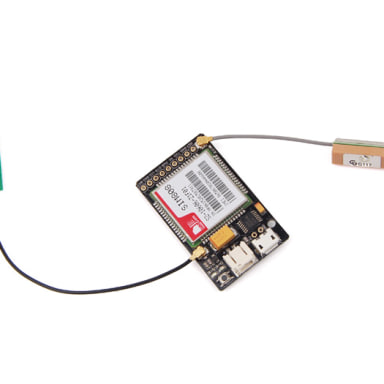
- GSM Antenna - this is an uFL GSM antenna connector, just connect it to a GSM antenna for receiving GSM signal.
- SIM - Card Holder - SIM card holder for standard SIM card
- EN_LEDs - this is the switch for Net and Status indicator. It is by default connected, if you want to save power and disable these LEDs, you can cut off the connection with a knife.
Pin Definitions
- PWR - this is soft power switch for the module, you can pull it to high level for at least 2s to power up or power down the module.
- RI - this pin will tell you whether the module is on and is there any calls and messages received. It will be pulled to high level when the module is on. And it will change to low for 120ms when a call or message is received.
- RXD / TXD - Serial port, the module uses it to send and receive commands and data. TXD is output, and RXD is input. They can be connected to the 3.3V and 5V level.
- VIO - this is the reference logic level for serial port of the module, the input voltage depends on the logical level of the microcontroller you use. If you use a 5V miccontroller like Arduino, you should have it be 5V, and a 3V logic microcontroller you should set it to 3V.
- BAT - this is the main power supply for the module, of input voltage from 3.4V to 4.4V. It is for connecting to Li-po battery. Without voltage regulator and smoothing circuit, please do not directly connect it to Arduino 5V.
- DTR - this is wake up pin for module in sleep mode. By default it has a high pull-up, and you can set the module into sleep mode by AT command “AT+CSCLK=1". In the meantime, the serial port will be disabled. To wake up the module and enable serial port, you can pull this pin to low level.
LED Status
| LED | Status | Function |
|---|---|---|
| Status Indicator (Green) | Off | Power of LoNet is off |
| On | Power of LoNet is on | |
| Net Indicator (Red) | Off | Power of LoNet is off |
| 64ms on/800ms off | LoNet can't find the network | |
| 64ms On/3000ms Off | LoNet has connected to network | |
| 64ms ON/3000ms Off | GPRS communication |
Usage Example
This is a example for testing AT command with Arduino Uno. If you use an USB to serial tools, you can use AT Command Tester or SSCOM32 to test AT commands.
Hardware Connections

Programming
// this sketch is used for testing LoNet with Arduino

          // Connect VIO to +5V
          // Connect GND to Ground
          // Connect RX (data into SIM800L) to Digital 11
          // Connect TX (data out from SIM800L) to Digital 10

          #include <SoftwareSerial.h>

          SoftwareSerial mySerial(10, 11); // RX, TX

          void setup()
          {
            // Open serial communications and wait for port to open:
            Serial.begin(9600);
            mySerial.begin(9600);

          }

          void loop() // run over and over
          {
            if (mySerial.available())
              Serial.write(mySerial.read());

            if (Serial.available())
            {
              while(Serial.available())
              {
                mySerial.write(Serial.read());
              }
              mySerial.println();
            }
          }
Set Baud
It is recommended to execute this process when first time to use the module. In the Serial Monitor columns of following tables, input of AT commands are in back, module returns values are in orange.
| Serial Monitor | Description |
|---|---|
| AT OK | Send command “AT" to synchronize baud rate. Serial port of module is by default set at auto-baud mode, and in this mode, it will not output any indications when the module is on. |
| AT+IPR=9600 OK | Set baud rate at 9600bps, supports baud rate from 1200bps to 115200bps. |
| AT&W OK | Save parameter setting. |
| AT+CPOWD=1 NORMAL POWER DOWN | Power down the module. |
| RDY +CFUN: 1 GPS Ready +CPIN: READY Call Ready SMS Ready | Turn on the module again by the power button, it will response status about GPS and GSM. |
| AT+CBC +CBC: 1,96,4175 OK | Inquire charging status and remaining battery capacity. |
| AT+CSQ +CSQ: 14,0 OK | Inquire GSM signal quality. |
Resource
- Design_Schematic
- SIM800_ATCommand_Manual
- SIM800L_HardwareDesign_Manual
- GPRS_Shield library on gitHub
- Adafruit_FONA_Library
Support
Any tech support, please contact support@deegou.com
Service
We do also provide PCB services ( Electronics design, prototype assembly and batch manufacturing ) If you have any requirements, please contact info@deegou.com
資料來源:https://www.seeedstudio.com/LoNet---Mini-GSM%26GPRS-Breakout-p-2366.html
Description
Please consider LoNet 800L - Mini GSM/GPRS Breakout as alternative product
This is not the replacement for the LoNet - Mini GSM/GPRS/GPS Breakout, but a simplified version without GPS function. It is based on SIM800L module, supports quad-band GSM/GPRS network, available for GPRS and SMS message data remote transmission.
The board features compact size and low current consumption. The size is only two times as large as a coin. With power saving technique, the current consumption is as low as 1mA in sleep mode. It communicates with microcontroller via UART port, supports command including 3GPP TS 27.007, 27.005 and SIMCOM enhanced AT Commands. It also has built-in level translation, so it can work with microcontrollor of higher voltage than 2.8V default. Beside, the board also supports A-GPS technique which is called mobile positioning and gets position by mobile network. This features make it can also be a tracker module.
This board is specially designed for project in a small box and powered by 3.7 li-po battery. If you want an Arduino shield, we are suggesting you pick up the SeeedStduio GPRS Shield.
Features:
- Quad-band 850/900/1800/1900MHz
- GPRS multi-slot class12 connectivity: max. 85.6kbps (down-load/up-load)
- GPRS mobile station class B
- Controlled by AT Command (3GPP TS 27.007, 27.005 and SIMCOM enhanced AT Commands)
- Supports Real Time Clock
- Supply voltage range 3.4V ~ 4.4V
- Supports A-GPS
- Supports 2.8V to 5.0V logic level
- Low power consumption, 1mA in sleep mode
- Compact size 23mm x 35mm x 5.6mm
- Standard SIM Card
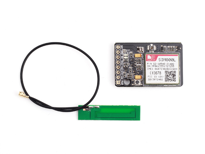
Packing List:
- 1 x LoNet - Mini GSM/GPRS Breakout
- 1 x GSM Antenna - 3dB Gain
Documents: