
官方授權台灣代理分銷
RPLidar A2M6 - 最薄的激光雷達


資料來源:https://www.seeedstudio.com/RPLidar-A2M6---The-Thinest-LIDAR-p-2919.html
Description
NOTE: It is recommended to use the upgraded version, RPLiDAR A2M6 360 Degree Laser Scanner Kit - 18M Range as your alternative choice (unit price $499).

Introduction
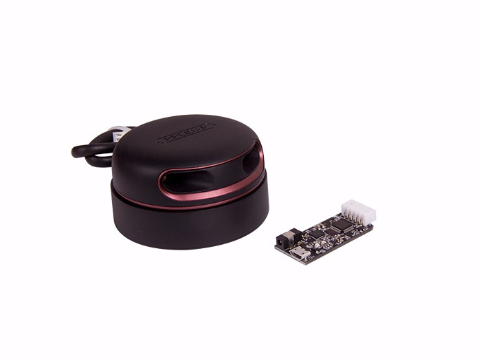
The RPLIDAR A2 is the next generation low cost 360 degree 2D laser scanner (LIDAR) solution developed by SLAMTEC. It can take up to 4000 samples of laser ranging per second with high rotation speed. And equipped with SLAMTEC patented OPTMAG technology, it breakouts the life limitation of traditional LIDAR system so as to work stably for a long time.
RPLIDAR A2M5/A2M6 is the enhanced version of 2D laser range scanner(LIDAR). The system can perform 2D 360-degree scan within a 16-meter range. The generated 2D point cloud data can be used in mapping, localization and object/environment modeling.
The typical scanning frequency of the RPLIDAR A2 is 10hz (600rpm). Under this condition, the angular resolution will be 0.9°. And the actual scanning frequency can be freely adjusted within the 5-15hz range according to the requirements of users.
The RPLIDAR A2 adopts the low cost laser triangulation measurement system developed by SLAMTEC, which makes the RPLIDAR A2 has excellent performance in all kinds of indoor environment and outdoor environment without direct sunlight exposure. Meanwhile, before leaving the factory, every RPLIDAR A2 has passed the strict testing to ensure the laser output power meet the standards of FDA Class I.
System connection
The RPLIDAR A2 consists of a range scanner core and the mechanical powering part which makes the core rotate at a high speed. When it functions normally, the scanner will rotate and scan clockwise. And users can get the range scan data via the communication interface of the RPLIDAR and control the start, stop and rotating speed of the rotate motor via PWM.

The RPLIDAR A2 comes with a rotation speed detection and adaptive system. The system will adjust the angular resolution automatically according to the actual rotating speed. And there is no need to provide complicated power system for RPLIDAR. In this way, the simple power supply schema saves the BOM cost. If the actual speed of the RPLIDAR is required, the host system can get the related data via communication interface.
The detailed specification about power and communication interface can be found in the following sections.
Mechanism
The RPLIDAR A2 is based on laser triangulation ranging principle and adopts the high-speed vision acquisition and processing hardware developed by SLAMTEC. The system ranges more than 4000 times per second. 
During every ranging process, the RPLIDAR emits modulated infrared laser signal and the laser signal is then reflected by the object to be detected. The returning signal is then sampled by vision acquisition system in RPLIDAR and the DSP embedded in RPLIDAR starts processing the sample data and outputs distance value and angle value between object and RPLIDAR via communication interface.
When drove by the motor system, the range scanner core will rotate clockwise and perform the 360-degree scan for the current environment.

Safety and Scope
The RPLIDAR A2 system uses a low power infrared laser as its light source, and drives it by using modulated pulse. The laser emits light in a very short time frame which can ensure its safety to human and pets, and it reaches Class I laser safety standard.

The modulated laser can effectively avoid the interference from ambient light and sunlight during ranging scanning process, which makes RPLIDAR work excellent in all kinds of indoor environment and outdoor environment without sunlight.
Data Output
During the working process, the RPLIDAR will output the sampling data via the communication interface. And each sample point data contains the information in the following table. If you need detailed data format and communication protocol, please contact SLAMTEC.
Figure 1 - 4 The RPLIDAR Sample Po int Data Information
| Data Type | Unit | Description |
| Distance | mm | Current measured distance value between the rotating core of the RPLIDAR and the sampling point |
| Heading | degree | Current heading angle of the measurement |
| Start Flag | (Bool) | Flag of a new scan |
| Checksum | The Checksum of RPLIDAR return data |

The RPLIDAR outputs sampling data continuously and it contains the sample point data frames in the above figure. Host systems can configure output format and stop RPLIDAR by sending stop command. For detailed operations please contact SLAMTEC.
High Speed Sampling Protocol and Compatibility
The RPLIDAR A2 adopts the newly extended high speed sampling protocol for outputting the 4000 times per second laser range scan data. Users are required to update the matched SDK or modify the original driver and use the new protocol to use the 4000 times per second mode of RPLIDAR A2. Please check the related protocol documents for details.
The RPLIDAR A2 is compatible with all the communication protocols of previous versions. Users can directly replace the previous RPLIDAR with RPLIDAR A2 and use it in the original system. But in this scenario, the RPLIDAR A2 will work in compatible mode and the system will take range 2000 times per second.
Application Scenarios
The RPLIDAR can be used in the following application scenarios:
General robot navigation and localization
Environment scanning and 3D re-modeling
Service robot or industrial robot working for long hours o Home service /cleaning robot navigation and localization
General simultaneous localization and mapping (SLAM)
Smart toy’s localization and obstacle avoidance
Specification
Measurement Performance
For Model A2M5/A2M6 Only
Figure 2 - 1 RPLIDAR Performance
| Item | Unit | Min | Typical | Max | Comments |
| Distance Range | Meter(m) | 0.2 | - | 16 | Based on white objects with 70% reflectivity |
| Angular Range | Degree | - | - | - | |
| Distance Resolution | mm | - | <0.5 | - | <1.5 meters |
| <1% of the distance | All distance range* | ||||
| Angular Resolution | Degree |
0.45 | 0.9 | 1.35 | 10Hz scan rate |
| Sample Duration | Millisecond(ms ) | - | 0.25 | - | - |
| Sample Frequency | Hz | 2000 | 4000 | 4100 | |
| Scan Rate | Hz | 5 | 10 | 15 | The rate is for a round of scan. The typical value is measured when RPLIDAR takes 400 samples per scan |
Note: the triangulation range system resolution changes along with distance.
Laser Power Specification
For Model A2M5/A2M6 Only
Figure 2 - 2 RPLIDAR Optical Specification
| Item | Unit | Min | Typical | Max | Comments |
Laser wavelength |
Nanometer(nm) | 775 | 785 |
795 | Infrared Light Band |
| Laser power | Milliwatt (mW) | - | 3 | 5 | Peak power |
| Pulse length | Microsecond(us) | 60 | 87 | 90 | - |
| Laser Safety Class | - | - | FDA Class I | - | - |
Note: the laser power listed above is the peak power and the actual average power is much lower than the value.
Optical Window
To make the RPLIDAR A2 working normally, please ensure proper space to be left for its emitting and receiving laser lights when designing the host system. The obscuring of the host system for the ranging window will impact the performance and resolution of RPLIDAR A2. If you need cover the RPLIDAR A2 with translucent materials or have other special needs, please contact SLAMTEC about the feasibility.

You can check the Mechanical Dimensions chapter for detailed window dimensions.
Coordinate System Definition of Scanning Data
The RPLIDAR A2 adopts coordinate system of the left hand. The dead ahead of the sensors is the x axis of the coordinate system; the origin is the rotating center of the range scanner core. The rotation angle increases as rotating clockwise. The detailed definition is shown in the following figure:

Communication interface
The RPLIDAR A2 uses separate 5V DC power for powering the range scanner core and the motor system. And the standard RPLIDAR A2 uses XH2.54-5P male socket. Detailed interface definition is shown in the following figure:

Figure 2 - 6 RPLIDAR External Interface Signal Definition
| Color | SignalName | Type | Description | Min | Typical | Max |
| Red | VCC | Power | Total Power | 4.9V | 5V | 5.5V |
| Yellow | TX | Output |
Serial port output of the scanner core | 0V | 3.3V | 3.5V |
| Green | RX | Input |
Serial port input of the scanner core | 0V | 3.3V | 3.5V |
| Black | GND | Power | GND | 0V | 0V | 0V |
| Blue | MOTOCTL | Input | Scan motor /PWM Control Signal (active high, internal pull down) | 0V | 3.3V | 5V |
Power Supply Interface
RPLIDAR A2 takes the only external power to power the range scanner core and the motor system which make the core rotate. To make the RPLIDAR A2 work normally, the host system needs to ensure the output of the power and meet its requirements of the power supply ripple.
For Model A2M5/A2M6 Only
Figure 2 - 7 RPLIDAR Power Supply Specification
| Item | Unit | Min | Typical | Max | Remark |
| Power Voltage | V | 4.9 | 5 | 5.5 | If the voltage exceeds the max value, it may damage the core |
| Power Voltage Ripple | mV | - | 20 | 50 | High ripple may cause the core working failure. |
| System Start Current | mA | - | 1200 | 1500 | The system startup requires relatively higher current. |
| Power Current | mA | TBD | 200 | 220 | 5V Power,power off |
| TBD | 450 | 600 | 5V Power,power on |
For more technical details, please visit the file below.
Technical Details
| Dimensions | 131mm x 101mm x 70mm |
| Weight | G.W 325g |
| Battery | Exclude |
Part List
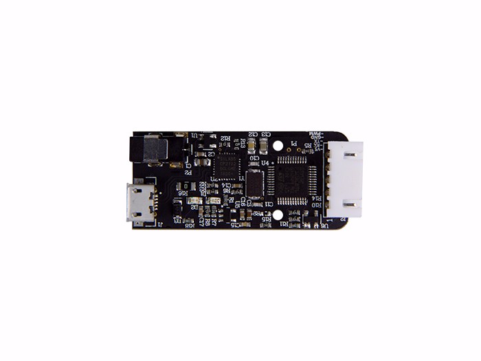
| RPLIDAR A2M6 | 1 |
| Serial board | 1 |
描述
介紹
RPLIDAR A2是由SLAMTEC開發的下一代低成本360度2D激光掃描儀(LIDAR)解決方案。高速旋轉速度每秒最多需要4000個激光測距。並配備SLAMTEC專利的OPTMAG技術,突破了傳統激光雷達系統的使用壽命,長期穩定工作。
RPLIDAR A2M5 / A2M6是2D激光測距掃描儀(LIDAR)的增強型。該系統可以在16米範圍內進行2D 360度掃描。生成的2D點雲數據可用於映射,定位和對象/環境建模。
RPLIDAR A2的典型掃描頻率為10hz(600rpm)。在這種情況下,角分辨率將為0.9°。實際掃描頻率可根據用戶要求在5-15hz範圍內自由調整。
RPLIDAR A2採用SLAMTEC開發的低成本激光三角測量系統,使得RPLIDAR A2在各種室內環境和室外環境中都能保持良好的性能,無需陽光直射。同時,在出廠前,每個RPLIDAR A2都通過了嚴格的測試,以確保激光輸出功率達到FDA Class I的標準。
系統連接
RPLIDAR A2由范圍掃描器芯和機械供電部分組成,使芯線高速旋轉。當功能正常時,掃描儀將順時針旋轉和掃描。用戶可以通過RPLIDAR的通訊接口獲取量程掃描數據,並通過PWM控制旋轉電機的啟動,停止和轉速。
RPLIDAR A2帶有轉速檢測和自適應系統。系統將根據實際轉速自動調整角度分辨率。並不需要為RPLIDAR提供複雜的電力系統。以這種方式,簡單的電源架構可以節省BOM成本。如果需要RPLIDAR的實際速度,主機系統可以通過通信接口獲取相關數據。
有關電源和通訊接口的詳細說明,請參見以下章節。
機制
RPLIDAR A2基於激光三角測距原理,採用SLAMTEC開發的高速視覺採集和處理硬件。系統每秒超過4000次。
在每個測距過程中,RPLIDAR發射調製的紅外激光信號,然後激光信號被被檢測物體反射。然後通過RPLIDAR中的視覺採集系統對返回信號進行採樣,嵌入RPLIDAR的DSP開始處理樣本數據,並通過通信接口輸出對象和RPLIDAR之間的距離值和角度值。
當由電機系統驅動時,量程掃描器芯將順時針旋轉,對當前環境進行360度掃描。
安全與適用範圍
RPLIDAR A2系統使用低功率紅外激光器作為其光源,並通過使用調製脈衝驅動它。激光器在非常短的時間內發光,可以確保其對人體和寵物的安全性,達到I級激光安全標準。
調製激光器可以有效避免測距掃描過程中環境光和陽光的干擾,使得RPLIDAR在各種室內環境和無陽光照射下的戶外環境中都能發揮出色的作用。
數據輸出
在工作過程中,RPLIDAR將通過通信接口輸出採樣數據。每個採樣點數據包含下表中的信息。如果您需要詳細的數據格式和通信協議,請聯繫SLAMTEC。
圖1 - 4 RPLIDAR Sample Po int數據信息
| 數據類型 | 單元 | 描述 |
| 距離 | 毫米 |
RPLIDAR的旋轉核心與採樣點之間的當前測量距離值 |
| 標題 | 度 | 當前的測量角度 |
| 開始標記 | (布爾) | 新的掃描的標誌 |
| 校驗 | RPLIDAR的校驗和返回數據 |
RPLIDAR連續輸出採樣數據,並包含上圖中的採樣點數據幀。主機系統可以配置輸出格式,並通過發送停止命令來停止RPLIDAR。詳細操作請聯繫SLAMTEC。
高速採樣協議和兼容性
RPLIDAR A2採用新擴展的高速採樣協議,輸出4000次/秒激光測距掃描數據。用戶需要更新匹配的SDK或修改原始驅動程序,並使用新協議使用RPLIDAR A2的每秒4000次模式。請查詢相關協議文件的詳細信息。
RPLIDAR A2與以前版本的所有通信協議兼容。用戶可以使用RPLIDAR A2直接替換以前的RPLIDAR,並將其用於原始系統。但在這種情況下,RPLIDAR A2將以兼容模式工作,系統每秒將佔用2000次。
應用場景
RPLIDAR可用於以下應用場景:
-
一般機器人導航和本地化
-
環境掃描和3D重建
-
服務機器人或長時間工作的工業機器人o家庭服務/清潔機器人導航和本地化
-
一般同時定位和映射(SLAM)
-
智能玩具的本地化和障礙物避免
規範
測量性能
-
僅適用於型號A2M5 / A2M6
圖2 - 1 RPLIDAR性能
| 項目 | 單元 | 敏 | 典型 | 馬克斯 | 註釋 |
| 距離範圍 | 米(m) | 0.2 | - | 16 | 基於70%反射率的白色物體 |
| 角度範圍 | 度 | - | - | - | |
| 距離分辨率 | 毫米 | - | <0.5 | - | <1.5米 |
| <1%的距離 | 所有距離範圍* | ||||
| 角度分辨率 |
度 |
0.45 | 0.9 | 1.35 | 10Hz掃描速率 |
| 樣品持續時間 | 毫秒(ms) | - | 0.25 | - | - |
| 採樣頻率 | 赫茲 | 2000 | 4000 | 4100 | |
| 掃描率 | 赫茲 | 五 | 10 | 15 | 速率是一輪掃描。當RPLIDAR每次掃描需要400個樣品時,測量典型值 |
注意:三角測量系統分辨率隨距離變化。
激光功率規格
-
僅適用於型號A2M5 / A2M6
圖2 - 2 RPLIDAR光學規範
| 項目 | 單元 | 敏 | 典型 | 馬克斯 | 註釋 |
|
激光波長 |
納米(nm) | 775 |
785 |
795 | 紅外燈帶 |
| 激光功率 | 千瓦(mW) | - | 3 | 五 | 峰值功率 |
| 脈衝長度 | 微秒(美國) | 60 | 87 | 90 | - |
| 激光安全等級 | - | - | FDA I類 | - | - |
注意:上面列出的激光功率是峰值功率,實際平均功率遠低於該值。
光學窗口
為了使RPLIDAR A2正常工作,請確保在設計主機系統時留出適合發射和接收激光的空間。測距窗口的主機系統模糊將影響RPLIDAR A2的性能和分辨率。如果您需要使用半透明材料覆蓋RPLIDAR A2或有其他特殊需求,請聯繫SLAMTEC有關可行性。
您可以查看機械尺寸章節了解詳細的窗口尺寸。
掃描數據的坐標系定義
RPLIDAR A2採用左手坐標系。傳感器前方的死角是坐標系的x軸;原點是范圍掃描器核心的旋轉中心。旋轉角度隨順時針方向旋轉而增加。具體定義如下圖所示:
通訊接口
RPLIDAR A2使用單獨的5V直流電源為範圍掃描儀內核和電機系統供電。而標準RPLIDAR A2使用XH2.54-5P插座。詳細界面定義如下圖所示:
圖2 - 6 RPLIDAR外部接口信號定義
| 顏色 | SignalName | 類型 | 描述 | 敏 | 典型 | 馬克斯 |
| 紅 | VCC | 功率 | 總功率 | 4.9V | 5V | 5.5V |
| 黃色 | TX |
產量 |
掃描儀核心的串口輸出 | 0V | 3.3V | 3.5V |
| 綠色 | RX |
輸入 |
掃描儀核心的串口輸入 | 0V | 3.3V | 3.5V |
| 黑色 | GND | 功率 | GND | 0V | 0V | 0V |
| 藍色 | MOTOCTL | 輸入 | 掃描電機/ PWM控制信號(高電平有效,內部下拉) | 0V | 3.3V | 5V |
電源接口
RPLIDAR A2採用唯一的外部電源為範圍掃描儀內核和使磁芯旋轉的電機系統供電。為了使RPLIDAR A2正常工作,主機系統需要確保電源的輸出並滿足其對電源紋波的要求。
-
僅適用於型號A2M5 / A2M6
圖2 - 7 RPLIDAR電源規格
| 項目 | 單元 | 敏 | 典型 | 馬克斯 | 備註 |
| 電源電壓 | V | 4.9 | 五 | 5.5 | 如果電壓超過最大值,可能會損壞磁芯 |
| 電源電壓波紋 | 毫伏 | - | 20 | 50 | 高紋波可能導致核心工作故障。 |
| 系統啟動電流 | 嘛 | - | 1200 | 1500 | 系統啟動需要相對較高的電流。 |
| 電源電流 | 嘛 | TBD | 200 | 220 | 5V電源,關機 |
| TBD | 450 | 600 | 5V電源,上電 |
數據通信接口
RPLIDAR A2採用3.3V-TTL串行端口(UART)作為通信接口。下表顯示了傳輸速度和協議標準。
圖2 - 8 RPLIDAR串口接口規格
| 項目 | 單元 | 敏 | 典型 | 馬克斯 | 評論 s | |||||||||
| 樂隊率 | BPS | - | 115200 | - | - | |||||||||
| 工作模式 | - | - | 8N1 | - | 8N1 | |||||||||
| 輸出高電壓 | 伏特(V) | 2.9 | - | 3.5 | 邏輯高 | |||||||||
| 輸出低電壓 | 伏特(V) | - | - | 0.4 | 邏輯低 | |||||||||
| 輸入高電壓 | 伏特(V) | 1.6 * | - |
最暢銷$ 27.15
$ 14.9
$ 89
$ 180
$ 360
$ 44
$ 59
入門套件") GrovePi + Raspberry Pi A +,B,B +&2,3(CE認證)入門套件 GrovePi + Raspberry Pi A +,B,B +&2,3(CE認證)入門套件
GrovePi + Raspberry Pi A +,B,B +&2,3(CE認證)入門套件 添加到購物車
$ 89.99
$ 44.45
$ 39.95
$ 49.9
 Seeed Studio BeagleBone綠色無線IOT開發者原型套件,適用於Google Cloud Platform Seeed Studio BeagleBone綠色無線IOT開發者原型套件,適用於Google Cloud Platform
Seeed Studio BeagleBone綠色無線IOT開發者原型套件,適用於Google Cloud Platform 添加到購物車
$ 99
技術細節
零件清單
問題與解答 RPLidar A2M6 - 最薄的激光雷達SKU 110990987
$ 600.00
50可用
船在
添加到購物車
$ 570.00 / 10 pcs +
 回到庫存時通知我
提交
|