
現貨供應最新開發模組
SARK-110 Antenna Analyzer 0.1 to 230 MHz 天線分析儀

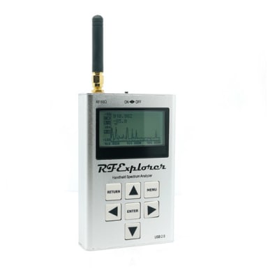
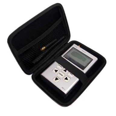
- Pocket size and lightweight
- Solid aluminum case
- Intuitive and easy to use
- Operating modes: Scalar Chart, Smith Chart, Single Frequency, Cable Test (TDR), Field Mode, Multi-band, Signal Generator, and Computer Control
- Excellent accuracy over a broad range of impedances
- Resolves the sign of the impedance
- Manual and automatic positioning tracking markers
- Transmission
- Circuit models function: transmission , capacitor and crystal
- Internal 2MB USB disk for the storage of measurements, screenshots, configuration and firmware upgrade
- Exports data in ZPLOTS-compatible format for further analysis on a PC
- SARK Plots client software for Windows
- Lifetime free firmware upgrades
- Open to community requested features
- Open source Software Development Kit (SDK) including a device simulator for development of user applications
代號
sark110
SKU 即原廠標號
109990076
原廠支援網站位於 http://www.sark110.com/,內容完整詳細,非常值得客戶直接瀏覽並下載各種相關軟體工具與 SDK。

|
The SARK-110 is a completely new design concept for an Antenna Analyzer. This is a truly pocket size device, so you can take it anywhere. It offers a gorgeous 3" high-resolution, active-matrix color display that allows information-rich diagrams. Its small size does not mean compromising the features and measurement performances. It has a frequency range from 0.1 to 230 MHz with 1 Hz of resolution. It has full vector measurement capability and accurately resolves the resistive, capacitive and inductive components of a load. The accuracy is excellent over a broad range of impedances and rivals any of the competitive devices in the market, see Test Results. The provided Open / Short/ Load calibration ensures the highest level of measurement accuracy. There is a transmission line calculator feature that allows adding or subtracting the effect of feed lines. The functionality of the SARK-110 is not restricted to antenna analysis, but it is a multifunction instrument featuring a TDR (Time Domain Reflectometer) mode which is intended for fault location and length determination in coaxial cables as well as a programmable RF signal generator. The analyzer is intended for standalone operation but also operates connected to a personal computer in combination with the SARK Plots client software for Windows, further enhancing the capabilities of the instrument. The SARK-110 allows you to quickly analyze any antenna over a user defined frequency range. In real time, you can see at a glance the resonant frequencies of the antenna, the VSWR, the complex impedance, reflection coefficient, return loss, and R-L-C as series or parallel equivalent circuits. You can test and tune coaxial cables and phasing stubs. You can adjust and test RF matching networks, antenna tuners, and RF amplifiers without applying power. Besides you can measure the impedance of components such as inductors, capacitors, and traps at RF frequencies. As a signal generator it is ideal for receiver calibration, sensitivity tests and signal tracing. The user interface has been designed to be intuitive and easy to use. On screen menus provide user guidance and the operation is mainly controlled by the two navigation keys. The graphical impedance displays provide a quick view of the antenna impedance characteristics on a user selected frequency range. This includes the graphical plot of two user selectable parameters in a rectangular diagram or the complex reflection coefficient in a Smith chart form. To help speed up measurements, two markers are available, both of which are user positionable or can operate in automatic tracking mode. The Multiband mode is a unique feature of the SARK-110 whereby it is able to display simultaneously the plot of an impedance parameter in four scalar charts. This feature is ideal for tuning multiband antennas. |
The SARK-110 provides as well a single frequency measurement mode which presents the complete impedance parameters at a user selectable frequency. To facilitate the reading, the analyzer displays graphically the R-L-C as both series and parallel equivalent circuit and the SWR as a convenient bar graph. The analyzer uses an internal 2MB flash disk for the storage and recall of measured parameters, screenshots, analyzer configuration and firmware updates. This disk is accessible via USB so the measured parameters can be downloaded to a PC for analysis using the ZPLOTS spreadsheet program or with SARK Plots client software for Windows. The SARK-110 is as well a hackable device. You can experiment with the device by writing an application using the provided open-source SDK. Besides the SDK includes a device simulator for the PC so you can easily debug your application before loading to the device. For more advanced users, the SARK-110 board provides connections to the STM32 SWD interface so you can use the ST-Link in-circuit debugger or equivalent to program or debug your software. With its pocket size, features, and simple user interface the SARK-110 offers a perfect device for HF/VHF impedance measurements for the RF experimenter and for the amateur radio operator. Whether you are at home in your shack or in the field during a field day or expedition. Please let us have your suggestions, through the site Join the Discussion as we are highly motivated to extend this device's functionality based on community requests.
|
Antenna Analyzer Mode:


Smith Chart Mode:

Single Frequency Mode:


Cable Test (TDR) Mode:

Field Mode:

Multi-band Mode:

Signal Generator Mode:

Menu Examples:


White Background:


資料來源:https://www.seeedstudio.com/SARK-110-Antenna-Analyzer-p-2487.html
Description
The SARK-110 is a completely new design concept for an Antenna Analyzer. This is a truly pocket size device, so you can take it anywhere. It offers a gorgeous 3” high-resolution, active-matrix color display that allows information-rich diagrams. The user interface has been designed to be intuitive and easy to use. On-screen menus provide user guidance and the operation is mainly controlled by the two navigation keys. The graphical impedance displays provide a quick view of the antenna impedance characteristics on a user selected frequency range.
Its small size does not mean compromising the features and measurement performances. It has full vector measurement capability and accurately resolves the resistive, capacitive and inductive components of a load for frequencies up to 230 MHz. The accuracy is excellent over a broad range of impedances and rivals any of the competitive devices in the market.
The functionality of the SARK-110 is not restricted to antenna analysis, but it is a multifunction instrument featuring a Time Domain Reflectometer (TDR) mode which is intended for fault location and length determination in coaxial cables; as well as a programmable RF signal generator. The analyzer is intended for standalone operation but also operates connected to a personal computer in combination with the SARK Plots client software for Windows, further enhancing the capabilities of the instrument.
Typical applications include checking and tuning antennas, impedance matching, components test, cable fault location, measuring coaxial cable parameters, and cutting coaxial cables to precise electrical lengths. As a signal generator it is ideal for receiver calibration, sensitivity tests and signal tracing.
Features
Pocket size and lightweight
Solid aluminum case
Operating modes: Scalar Chart, Smith Chart, Single Frequency, Cable Test (TDR), Field Mode, Multi-band, Signal Generator, and Computer Control
Excellent accuracy over a broad range of impedances
OSL Calibration
Resolves the sign of the impedance
Manual and automatic positioning tracking markers
Transmission line add and subtract
Circuit models function: transmission line, inductor, capacitor and crystal
Internal 2MB USB disk for the storage of measurements, screenshots, configuration and firmware update
SARK Plots client software for Windows
Export data in ZPLOTS compatible format for further analysis on the PC
Lifetime free firmware upgrades available, open to community requested features
Open source SDK including a device simulator for user applications development
Specification
Frequency range: 0.1 to 230MHz with 1Hz resolution
Complex impedance (series and parallel) and reflection coefficient in rectangular and polar form, VSWR, return loss, cable losses, reflection power percentage, quality factor, equivalent capacitance, equivalent inductance
Features common to most modes: presets for amateur bands; adjustable reference impedance; save to disk and recall functions; three available fixed scale options and automatic scaling; add/subtract transmission line; black and white color themes; adjustable plot trace widths
Scalar Chart mode: graphical plot of two user selected parameters in a rectangular chart; two markers with manual or automatic positioning; display detailed parameters for center frequency or any of the two marker positions
Smith Chart mode: plots complex reflection coefficient in Smith Chart form; two markers with manual or automatic positioning; display detailed parameters for center frequency or any of the two marker positions
Single Frequency mode: display all parameters for a single frequency; graphical representation of series and parallel impedance equivalent; VSWR audio feedback; circuit models
Cable Test mode: time domain reflectometer; max. distance: about 250 m; displays step and impulse response
Field mode: graphical plot of one user-selected parameter in a scalar chart with enhanced legibility; display max and min values
Multi-band mode: display four independent charts simultaneously
Signal Generator mode: precise RF signal generator with 1 Hz resolution; programmable output level from -73 dBm to -10 dBm; continuous and frequency sweep modes; linear, logarithmic, bi-linear, and bi-logarithmic sweep modes
Automatic tracking modes: peak min, peak max, absolute min, absolute max, value cross any, value cross up, value cross down
Calibration: automated open Open/Short/Load calibration; 400 calibration points; frequency calibration
Display: 3” TFT LCD with 400 x 240 resolution
Power: Lithium-Polymer battery rechargeable from USB; battery charge status indicator; automatic power-off mode
RF output: connector type MCX, output power -10dBm (50-ohm load)
Storage: internal 2MB USB compatible disk
USB: Mini-B receptacle; mass storage class (storage) and HID class (computer control)
Processor: 72 MHz STM32 MCU, 256 KB Flash, 48KB SRAM
Measurement architecture: single conversion superheterodyne; two independent and synchronized measurement channels with 12-bit
If you have any technical questions please contact the designerdirectly.
There is online community forum here and in Facebook as well.
For any technical support or suggestion, please kindly go to our forum.
Technical Details
| Dimensions | 124mm x 80mm x 40mm |
| Weight | G.W 168g |
| Battery | Lithium Cells / Batteries contained in equipment UN3481 - PI967 |
Part List
| SARK-110 Antenna Analyzer | 1 |
| SNA male plug to SMA female jack cable adapter | 1 |
| MCX plug to SMA female jack connector adapter | 1 |
Documents