
現貨供應最新開發模組
LinkIt Smart 7688 Duo


- 580 MHz MIPS CPU
- Single input single output(1T1R) Wi-Fi 802.11 b/g/n (2.4G)
- Pin-out for GPIO, I2C, I2S, SPI, SPIS, UART, PWM and Ethernet Port
- 32MB Flash and 128MB DDR2 RAM
- USB host
- Micro SD slot
- Support for Arduino API (ATmega32U4)
代號
linkit-smart-duo
SKU 即原廠標號
102110017
定價
特價
600 (含營業稅)
暫無庫存
原廠連結:http://wiki.seeed.cc/LinkIt_Smart_7688_Duo/
LinkIt Smart 7688 Duo
Introduction
LinkItTM Smart 7688 Duo(a compact controller board) is an open development board based on MT7688(datasheet) and ATmega32u4. The board is compatible with Arduino Yun sketches and is based on the OpenWrt Linux distribution. The board is designed especially to enable prototyping of Rich Application IoT devices for smart home or office[1]. As it is compatible well with Arduino, you can use different features from Arduino Yun and LinkIt Smart 7688 Duo[2]. This will help you build rich applications based on various, robust and compiled Arduino Yun sketches. The board offers you the memory and packet storage to enable robust video processing. The platform also offers options to create device applications in Python, Node.js and C programming languages.
This board is only a part of MediaTek LinkItTM Smart 7688 platform which includes other development boards.
Only one controller can be the main controller of the board at a time.
Note
- This page only guides you to get started with this development board. For a complete guide, please refer to Resources.
- Only one controller can be the main controller of the board at a time.
- This board is only a part of MediaTek LinkItTM Smart 7688 platform which includes other development boards.
Features
- 580 MHz MIPS CPU
- Single input single output(1T1R) Wi-Fi 802.11 b/g/n (2.4G)
- Pin-out for GPIO, I2C, I2S, SPI, SPIS, UART, PWM and Ethernet Port
- 32MB Flash and 128MB DDR2 RAM
- USB host
- Micro SD slot
- Support for Arduino API (ATmega32U4)
Application ideas
- IoT/Gateway Device
- Robotics
- Teaching and learning
Specification
- MPU
- Chipset: MT7688AN
- Core: MIPS24KEc
- Clock Speed: 580MHz
- Working Voltage: 3.3V
- MCU
- Chipset: ATmega32U4
- Core: Atmel AVR
- Clock Speed: 8MHz
- Working Voltage: 3.3V *Memory
- Flash: 32MB
- RAM: 128MB DDR2 *GPIO
- Pin Count: 3(MT7688AN), 24(ATmega32U4)
- Voltage: 3.3V
- PWM
- Pin Count: 8(Atmega32U4)
- Voltage: 3.3V
- Max. Resolution: 16 bits(customizable)
- ADC
- Pin Count 12(ATmega32U4)
- Resolution: 10 bits
- External Interrupts: 8
- SPI/SPIS
- Pin numbers: S0, S1, S2, S3
- Max Speed: 4MHz
- I2C
- Pin Number: D2/D3
- Speed: 400KHz
- UART Lite
- 1 for ATmega32U4, 1 for MT7688AN
- Pin Number: P8/P9(MT7688AN), D0/D1(ATmega32U4)
- USB Host
- Pin Number: P6/P7
- Connector Type: Micro-AB
- Communication
- Wi-Fi: 1T1R 802.11 b/g/n (2.4G)
- Ethernet: 1-port 10/100 FE PHY
- Pin Numbers: P2/P3/P4/P5
- User Storage: SD Card Micro SD/SDXC
- Size: 60.8x26.0mm
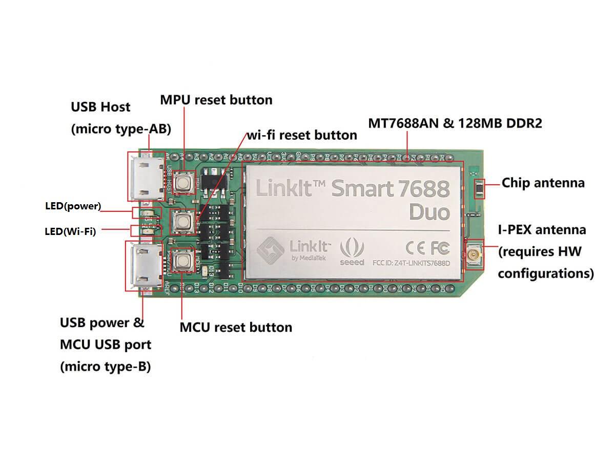
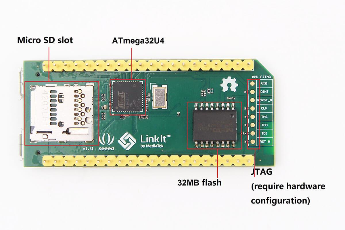
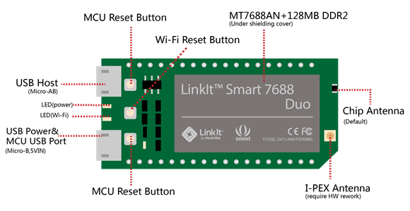
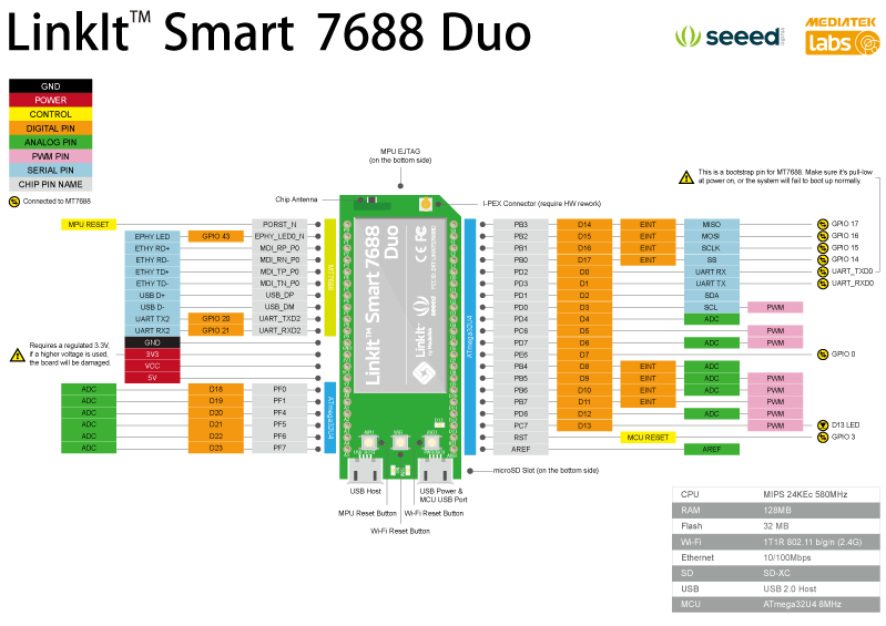
Hardware Overview
Getting started
Connecting to the embedded operating system
Note
There are two ways described in the manual. In this case, we only show an advanced method (using USB to Serial adapter) which might seem a little harder. But, you will benefit a lot from it in the long run.
Materials required
- LinkIt Smart 7688 x 1
- USB cable (type A to micro type-B) x 1
- USB to Serial adapter x 1
- Jumper wires x 3
On Windows
1.Install PuTTy. PuTTY provides a system console environment using SSH (Secure Socket Shell) to access development board’s operating system.
2.Install Bonjour Print Service (For Windows 7, Windows 8, Windows 10).
3.Install driver. If you are using a USB cable based on FTDI chip please download and install its driver from here. If you are having problems with the latest driver, try installing an older version.
4.Next, you will need to connect the Serial to USB cable to LinkIt Smart 7688’s UART pins as shown in the following table:
| Pin on USB adapter | Corresponding Pin to be connected on LinkIt Smart 7688 |
|---|---|
| Pin RX | Pin 8 |
| Pin TX | Pin 9 |
| Pin GND | Pin GND |
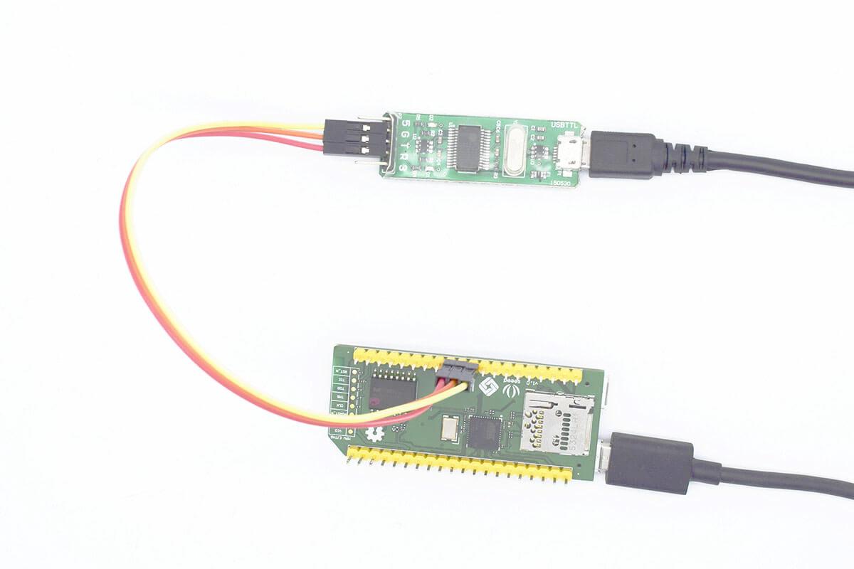
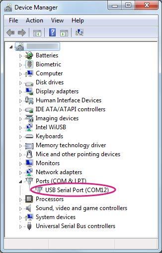
5.After connecting the Serial to USB cable, open the device manager and notice the COM port number as shown in Figure 22. This number may vary on different computers.
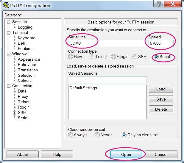
6.Launch the PuTTY terminal and enter the COM port number of the USB device found in the device manager, click on the Serial radio button, type 57600 in Speed box and click Open, as shown in Figure 23.
7.To exit the system console, click the close icon on top right of the PuTTY windows.
On Mac
1.Install the driver if needed. Check the cable manufacturer’s website for driver requirements on Mac and installation instructions.
2.Plug-in the cable to PC/Laptop and connect the cable to LinkIt Smart 7688.
3.Open a Terminal session.
4.Type ls /dev/cu* in the Terminal. You should see a list of devices. Look for something like cu.usbserial-XXXXXXXX where XXXXXXXX is usually a random identifier. This is the serial device used to access the system console.
For example:
$ls /dev/cu*

/dev/cu.Bluetooth-Incoming-Port

/dev/cu.Bluetooth-Modem

/dev/cu.pablop-WirelessiAP

/dev/cu.usbserial-A6YMCQBR
5.Use the screen utility to connect to the serial port and set the baudrate to 57600. This is because the baudrate of the system console is 57600 by default. For example:
$screen /dev/cu.usbserial-XXXXXXXX 57600
6.Now you should be connected to the system console. Press ENTER in the Terminal to bring up the prompt. You will notice that the prompt has become different from your OS X Terminal application, it is the LinkIt Smart 7688 prompt and it looks like the following:
root@myLinkIt:/#
7.You are ready to make changes to the LinkIt Smart 7688 system through this console.
On Linux
1.Install the driver if needed. Check the cable manufacturer’s website for driver requirements on Linux and installation instructions.
2.Plug-in the cable and connect the cable to LinkIt Smart 7688 Duo.
3.Open a Terminal session.
4.Type ls /dev/ttyUSB* in the Terminal. You should see a list of devices. Look for something like cu.usbserial-XXXXXXXX where XXXXXXXX is usually a random identifier. This is the serial device used to access the system console. For example:
$ls /dev/ttyUSB*
/dev/ttyUSB0
5.Use the screen utility to connect to the serial port and set the baudrate to 57600. This is because the baudrate of the system console is 57600 by default. For example:
$sudo screen /dev/ttyUSB0 57600
6.Now you should be connected to the system console. Press ENTER in the Terminal to bring up the prompt. You will notice that the prompt has become a different regular application, it is the LinkIt Smart 7688 prompt and it looks like the following:
root@myLinkIt:/#
7.You are ready to make changes to the LinkIt Smart 7688 system through this console.
Running the Blink example
Materials Required
- LinkIt Smart 7688 x 1
- USB cable (type A to micro type-B) x 1
- USB to Serial adapter x 1
- Jumper wires x 3
Get Blink RUN
1.Power up your board with a micro-USB cable (only connect the USB Power interface, rather than the USB Host interface).
2.Launch PuTTy and connect to system with USB to Serial adapter as shown in previous sections.

3.Type python /IoT/examples/blink-gpio44.py and press Enter to run the Blink example.
4.After around 2 seconds, you will notice that the Wi-Fi LED blinks steadily.
5.In the system console, type CTRL + C, this will terminate the example.
Connect to the Internet (Switch to Station mode)
There are two Wi-Fi modes, i.e. AP mode and Station mode. Refer this for the differences between them.
1.Power up the board with a micro-USB cable.
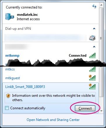
2.Open the Wi-Fi connection utility on your computer and connect to the access point named LinkIt_Smart_7688_XXXXXX. XXXXXX is a kind of hardware identifier which varies from board to board.
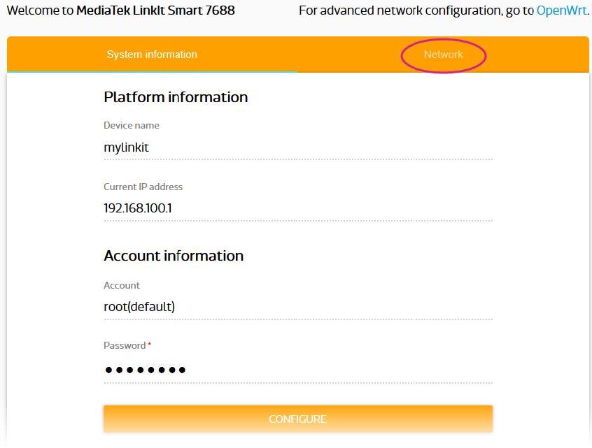
3.Open a browser with URL mylinkit.local/ or 192.168.100.1, set the password for root and sign in. Click Network on the upper right.
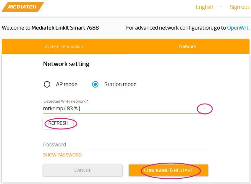
4.Select the Station mode and click Refresh or downward arrow on the right to find the AP to connect to. After you have selected the AP, enter password if required. Click Configure & Restart to finish as shown below. Then wait for around 30 seconds to switch mode.
5.Launch PuTTy and connect to the system with USB to Serial adapter as shown in the previous section.
6.Type ifconfig and find the IP address of inet addr as shown below:
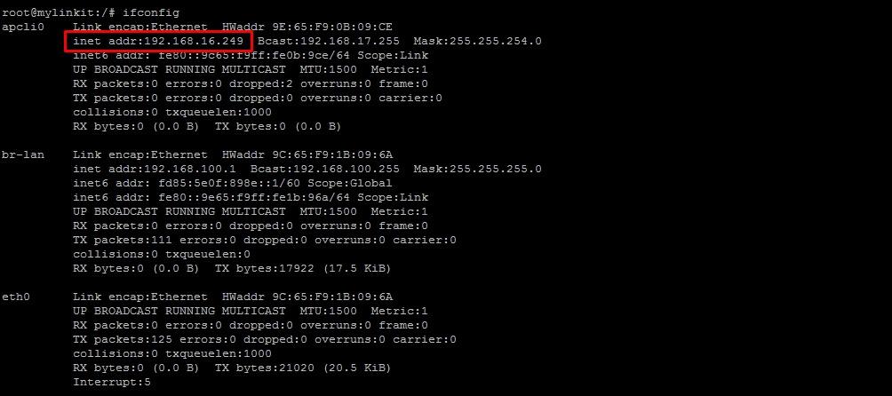
Note
It will still enter the Station mode after rebooting the system. Press wi-fi button at least 5 seconds to switch back to AP mode. Note: It will be needed to reboot the embeded OS by using reboot command.
7.Type the IP in a new Tab of browser and you can login to Web user interface to configure the system.
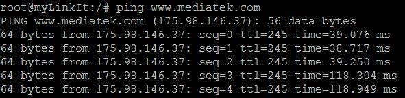
8.Now both the host computer and LinkIt Smart 7688 are connected to internet. Type ping www.mediatek.com in console and you will get:
9.Now you can use internet to configure your system on development board.
Installing Arduino programming environment
This development board has features that are compatible with Arduino. So you can transfer your Arduino code to 7688 platforms which makes prototyping process quicker. In this section, we will show you how to build an Arduino programming environment.
Download and install Arduino IDE
You can install Arduino IDE 1.6.5 on your computer.
Configure Arduino IDE for LinkIt Smart 7688 Platform
Installing developed board support package
Arduino IDE 1.6.5 supports third party board integration using the Board Manager tool. LinkIt Smart 7688 development board is a plug-in to Arduino IDE and you will need to install the board package so that Arduino supports LinkIt board. Please follow the steps below:
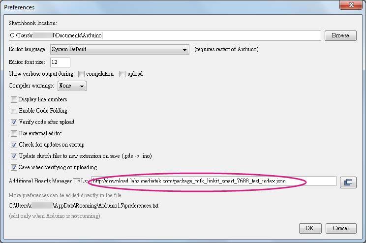
1.In Arduino IDE, on the File menu click Preferences then insert
http://download.labs.mediatek.com/package_mtk_linkit_smart_7688_test_index.json
to the Additional Boards Manager URLs field:
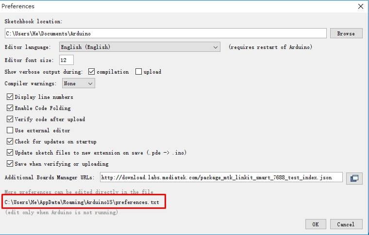
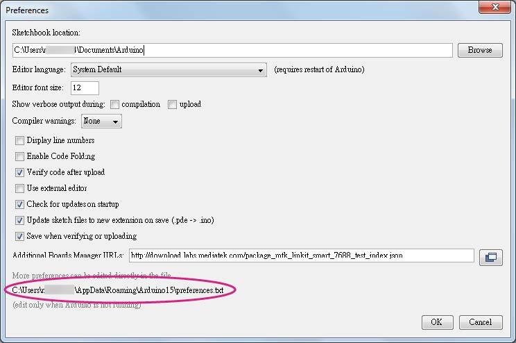
2.Make sure your computer is connected to the internet. Download LinkIt, decompress it and copy the files into the folder packages which gets same location with file Preferences.txt. Click following red rectangle marked section to open file location of Preferences.txt.
3.In the Arduino Tools menu point to Board.
4.There should now be a LinkIt Smart 7688 item appearing in the boards list on the Boards Manager and choose port with COMxx (LinkIt Smart 7688 Duo).
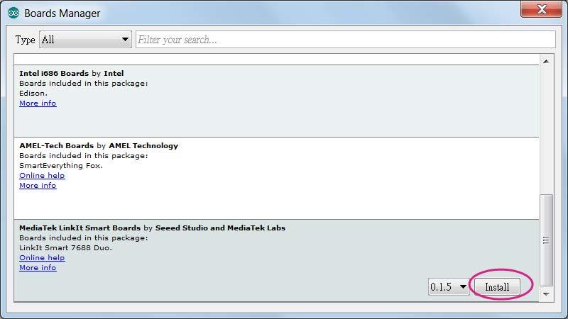
5.The installation is completed.
Installing LinkIt Smart 7688 Duo COM Port Driver
After installing the board package, connect LinkIt Smart 7688 Duo to your computer and you should see a USB serial COM port in the device manager with the following port ID:
- Boot loader COM port: VID=0x0E8D, PID=0xAB00
- Arduino Sketch COM port: VID=0x0E8D, PID=0xAB01
Next, you will need to install drivers depending on your operating system. The steps are:
Note
For Windows 10, there is no need to install a driver. However, extra steps are needed to ensure Windows 10 recognizes the board. Connect LinkIt Smart 7688 Duo to your Windows 10 machine, then quickly press the MCU reset button twice within 700 milliseconds. The system should now recognize LinkIt Smart 7688 Duo as a USB Serial Device (COM5). The number 5 may be different on different machines. You only need to do this the first time the board is connected to your Windows machine.
Note
For Windows 8, the system may block the driver installation. Follow this link to know how to disable driver signature enforcement on Windows 8. After the signature enforcement is disabled, follow the steps in Windows 7 below to install the driver.
Note
For Windows 7, find the Serial COM port INF driver in the following path. You can also install it from here.
{ARDUINO_IDE_PREFERENCE_LOCATION}Arduino15/packages/LinkIt/hardware/avr/0.1.5/driver/linkit_smart_7688.inf
You will find the Arduino preference location at File -> Preferences, see the preference.txt path.
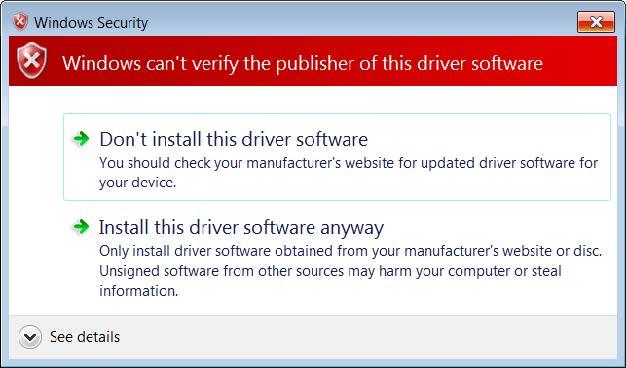
Right click on the linkit_smart_7688.inf and select install, a security windows appears and click Install this driver software anyway. This completes the driver installation.
- For Ubuntu Linux, it should work without installing a driver. LinkIt Smart 7688 should be in /dev folder and mounted as ttyUSB0. The number 0 may be different on each Ubuntu machine.
- For OS X, it is also not required to install a driver, LinkIt Smart 7688 Duo is mounted as a serial device under/dev/tty.usbmodem1413. The number 1413 may be different on each OS X machine.
Demo: A Hello world example
Note
To avoid running out of memory during native application developments, you should setup the native application development environment in a more powerful host environment that enables you to cross-compile the executable format of the LinkIt Smart 7688 target instead. The following table shows an overview of the LinkIt Smart 7688 programming languages and the related development environments on host computer.
Python
1.Use FileZilla and refer to this tutorial, the server IP(replace host name) address is the inet addr found in previous Switch to Station mode section, the username is root and password is password you set in that section.
2.Open a text editor, copy and paste the below example code and save it as helloworld.py.
print "Hello World!"
3.Copy the file helloworld.py into system on target development environment (LinkIt Smart 7688) with FileZilla, place it under the folder root.
4.Launch PuTTy and connect to system with USB to Serial adapter.
5.Set working directory to /root and enter python helloworld.py to execute.
6.Now you can see Hello World! printed in console.
Arduino
On host computer(Arduino side)
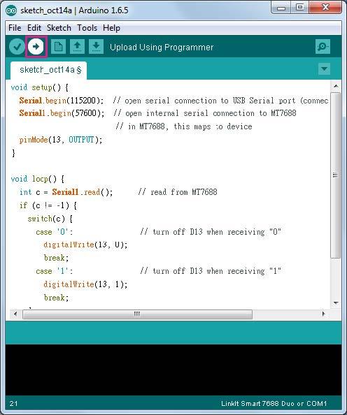
The MCU side is written as an Arduino sketch. In this example, the sketch simply listens to the command sent from the MPU (Linux) side and switches the on-board LED accordingly.
1.First, connect the LinkIt Smart 7688 Duo to your PC, then open Arduino IDE and paste the following sketch code into the IDE:
void setup() {
    Serial.begin(115200); // open serial connection to USB Serial port (connected to your computer)
    Serial1.begin(57600); // open internal serial connection to MT7688
    // in MT7688, this maps to device
    pinMode(13, OUTPUT);
}
void loop() {
    int c = Serial1.read(); // read from MT7688
    if (c != -1) {
        switch(c) {
        case '0': // turn off D13 when receiving "0"
            digitalWrite(13, 0);
            break;
        case '1': // turn off D13 when receiving "1"
            digitalWrite(13, 1);
            break;
        }
    }
}
2.Then choose the correct COM port from the IDE (check your device manager) by clicking Tools -> Port.
3.Upload the sketch to the board. Note the board is not blinking yet - you will need to write a program in the Linux side to make it blink, which is the next step.
On development board(Linux side)
1.Use a text editor of your choice and create a new file(a Python file), then copy the following code and save it.
import serial
import time
s = None
def setup():
global s
# open serial COM port to /dev/ttyS0, which maps to UART0(D0/D1)
# the baudrate is set to 57600 and should be the same as the one
# specified in the Arduino sketch uploaded to ATmega32U4.
s = serial.Serial("/dev/ttyS0", 57600)
def loop():
# send "1" to the Arduino sketch on ATmega32U4.
# the sketch will turn on the LED attached to D13 on the board
s.write("1")
time.sleep(1)
# send "0" to the sketch to turn off the LED
s.write("0")
time.sleep(1)
if __name__ == '__main__':
setup()
while True:
loop()
2.Execute this Python program in the system console - this program basically writes string of 1 and 0 to the /dev/ttyS0 port which maps to Serial1 interface in Arduino. The Arduino sketch that was uploaded in the previous section will receive the string and then blink the on-board LED accordingly.
You can now extend the Arduino sketch to drive other devices such as PWM, I2C devices and synchronize the states by extending the command messages between Arduino and the Linux side. If more peripheral types need to be included, you can use some external libraries to implement the communication protocol. One such protocol - Firmata is described in the following section.
Resources
- Hardware Schematic files
- Manual
- OpenWrt
- MediaTek LinkIt? Smart 7688 Resources:
- How to flash the firmware via a USB drive
- Certificates
Help us make it better
Thank you for choosing Seeed. A couple of months ago we initiated a project to improve our documentation system. What you are looking at now is the first edition of the new documentation system. Comparing to the old one, here is the progresses that we made:
- Replaced the old documentation system with a new one that was developed from Mkdocs, a more widely used and cooler tool to develop documentation system.
- Integrated the documentation system with our official website, now you can go to Bazaar and other section like Forum and Community more conveniently.
- Reviewed and rewrote documents for hundreds of products for the system’s first edition, and will continue migrate documents from old wiki to the new one.
An easy-to-use instruction is as important as the product itself. We are expecting this new system will improve your experience when using Seeed’s products. However since this is the first edition, there are still many things need to improve, if you have any suggestions or findings, you are most welcome to submit the amended version as our contributor or give us suggestions in the survey below, Please don’t forget to leave your email address so that we can reply.
Happy hacking
資料來源:https://www.seeedstudio.com/LinkIt-Smart-7688-Duo-p-2574.html
Description
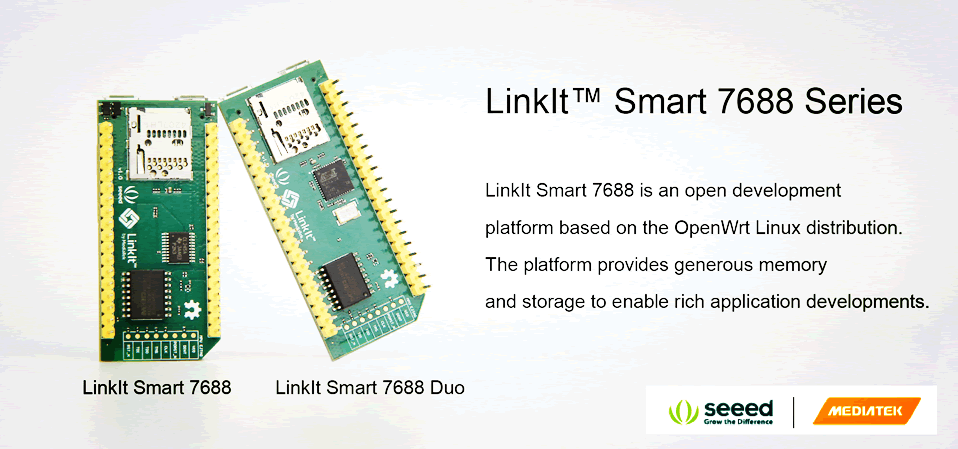
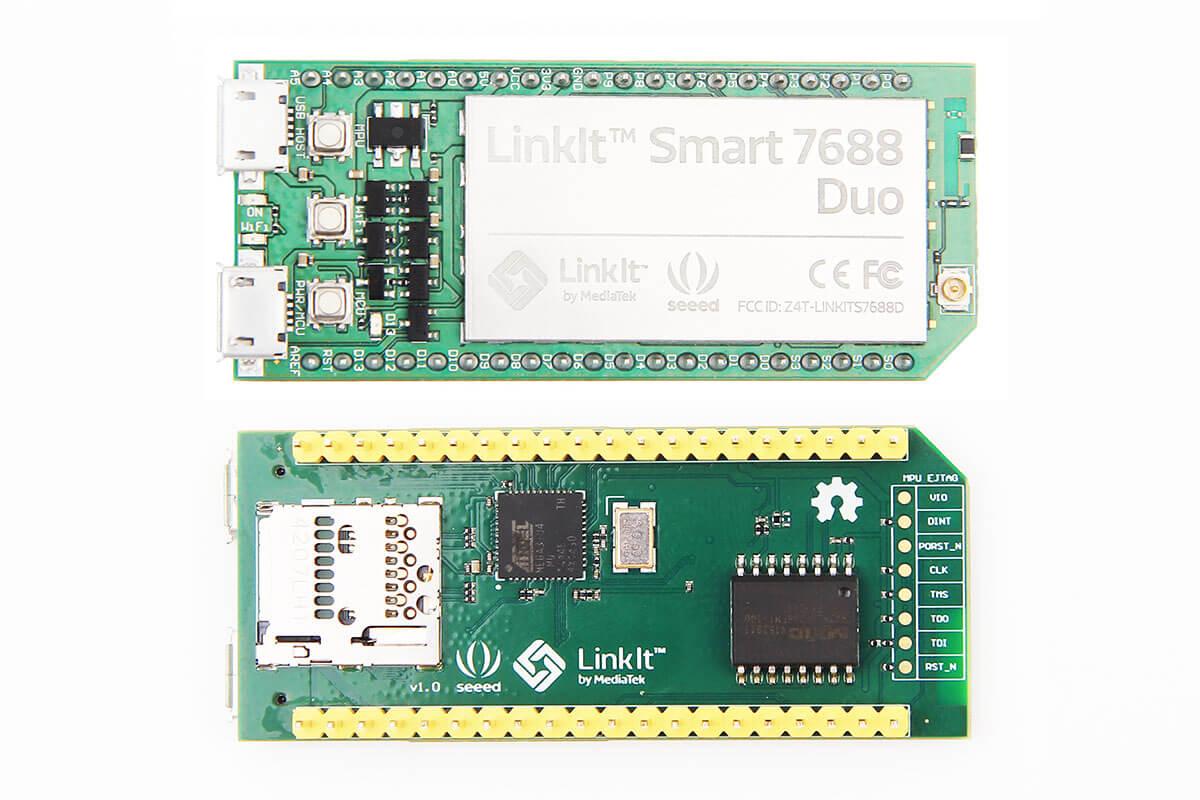
The Linklt Smart 7688 development platform offers two developments boards:
Linklt Smart 7688: MPU only. Powered by Media Tek MT7688.
Linklt Smart 7688 Duo: MPU and MCU. Powered by Media Tek MT7688 and ATmega 32U4.
What is LinkIt Smart 7688 Duo
LinkIt Smart 7688 Duo is an open development board compatible with Arduino Yún sketches, based on the OpenWrt Linux distribution, MT7688 and ATmega32u4. The board is designed especially to enable the prototyping of Rich IoT Application for smart house or office. Since it is compatible with Arduino, this allows you to use different features from Arduino Yún and LinkIt Smart 7688 Duo, which will help you build rich applications based on various, robust and compiled Arduino Yún sketches. The board offers you the memory and packet storage to enable robust video processing. The platform also offers options to create device applications in Python, Node.js and C programming language.
LinkIt Smart 7688 duo is a co-design product by Seeed Studio and MediaTek. It brings together the parties' knowledge in open hardware and industry leading reference designs for IoT devices to create this powerful development board.
LinkIt Smart 7688 duo is fully supported on the MediaTek Labs site: check out the LinkIt sectionandregister here to download the SDK, participate in the Forums, and more.
Note (important)
In order to protect the product from improper operation, please pay attention to below notes.
Choose more reliable power adapter with stable output.
Recommended conditions of power input source for 7688:
1. Overshoot voltage of power input should not over 5.5.
2. Voltage wave should be within ±100mV of rated voltage.
Features
580 MHz MIPS CPU
Single input single output(1T1R) Wi-Fi 802.11 b/g/n (2.4G)
Pin-out for GPIO, I2C, SPI, SPIS, UART, PWM and Ethernet Port
32MB Flash and 128MB DDR2 RAM
USB host
Micro SD slot
Support for Arduino (ATmega32U4)
Specifications
| Category | Feature | Specification |
|---|---|---|
| MPU | Chipset | MT7688AN |
| Core | MIPS24KEc | |
| Clock speed | 580MHz | |
| Working voltage | 3.3V | |
| MCU | Chipset | ATmega32U4 |
| Core | Atmel AVR | |
| Clock speed | 8MHz | |
| Working voltage | 3.3V | |
| PCB Size | Dimensions | 60.8 x 26 mm |
| Memory | Flash | 32MB |
| RAM | 128MB DDR2 | |
| Power Source | USB Power | 5V (USB micro-B) |
| VCC | 3.3V (Pin Breakout) | |
| GPIO | Pin Count | 3 (MT7688AN) 24 (ATmega32U4) |
| Voltage | 3.3v | |
| PWM | Pin Count | 8 (ATmega32U4) |
| Voltage | 3.3v | |
| Max. Resolution | 16 bits (customizable) | |
| Maximum Frequency@Resolution | 31.25kHz@8-bit, Timer 0 (4 sets) | |
| 2MHz@2-bit,122Hz@16-bit, Timer 1 & 3 (4 sets) | ||
| 187.5kHz@8-bit, 46.875kHz@10-bit, Timer 4 (6 sets) | ||
| ADC | Pin Count | 12 (ATmega32U4) |
| Voltage | 3.3v | |
| External Interrupts | Pin Count | 8 (ATmega32U4) |
| SPI/SPIS | Set count | 1 (ATmega32U4) |
| Pin numbers | S0, S1, S2, S3 | |
| Max. Speed | 4 MHz | |
| I2C | Set count | 1 |
| Pin numbers | D2, D3 | |
| Speed | 400K | |
| UART Lite | Set count | 1 (ATmega32U4) |
| 1 (MT7688AN) | ||
| Pin numbers | P8, P9 (MT7688AN) | |
| D0, D1 (ATmega32U4) | ||
| Max. Speed | 0.5 Mbps (MT7688AN) | |
| 0.5 Mbps (ATmega32U4) | ||
| USB Host | Set count | 1 (MT7688AN) |
| Pin numbers | P6, P7 | |
| Connector type | Micro-AB | |
| Communication | Wi-Fi | 1T1R 802.11 b/g/n (2.4G) |
| Ethernet | 1-port 10/100 FE PHY | |
| Pin numbers | P2, P3, P4, P5 | |
| User Storage | SD Card | Micro SD SDXC |
Schematic Diagram
Technical Details
| Dimensions | 56mm x 26mm x 18mm |
| Weight | G.W 14g |
| Battery | Exclude |
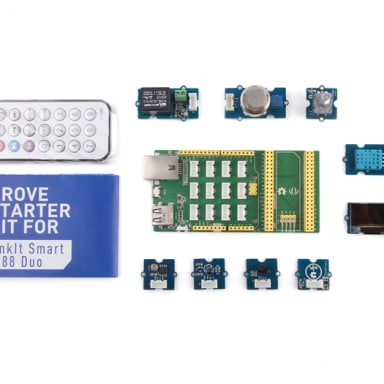
Part List
| LinkIt Smart 7688 Duo | 1 |
Documents
Learn

[Wiki]LinkIt Smart 7688 Duo
LinkItTM Smart 7688 Duo(a compact controller board) is an open development board based on MT7688(datasheet) and ATmega32u4. The board is compatible with Arduino Yun sketches and is based on the OpenWrt Linux distribution.

A Social Printer for Special People
A Social Printer for Special People

Facebook Like Monitor
A device to get how many likes at your Facebook page

Smart router with WiFi Connection Visualization
Smart router with WiFi Connection Visualization