
現貨供應最新開發模組
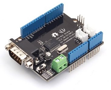
CAN-BUS Shield v1.2 汽車檢測控制擴展板


原廠連結:http://www.seeedstudio.com/wiki/index.php?title=CAN-BUS_Shield_拓展板&uselang=zh
產品簡介
CAN-BUS是一種常見的工業總線,因為其支持較長的行駛距離,中等的通信速度和高可靠性。它通常被發現在現代機床和汽車診斷總線。CAN-BUS拓展板採用MCP2515的CAN總線控制器,SPI接口和MCP2551 CAN收發器,與你的Arduino的/ Seeeduino進行通信。隨著OBD-II轉換線和OBD-II庫的完善,你可以建立一個車載診斷裝置或數據記錄器。
功能特性
- CAN V2.0B 傳輸速率高達 1 Mb/s
- SPI 接口傳輸速率高達 10 MHz
- 標準(11位)和拓展(29位)數據傳輸
- 兩個具有優先級信息存儲的接受緩存
- 9 針工業標準的sub-D接口
- 兩個LED指示燈
參數規格
電壓:4.8~5.2V
尺寸:68x53mm
淨重:50g

Note:
When you use more than two CAN Bus Shield in one net, you should concern about the impedance.
You can just cut P1 in the PCB with a knife, or just remove R3 on the PCB.
Demonstration

1. Download the CAN-BUS Source code file for Arduino 1.0 and release it in the libraries file in the Arduino-1.0 program.: ..\arduino-1.0\libraries.
If the folder name include "-master", just remove it.
2. Open the Arduino-1.0, and you will find 3 examples: receive_check ,send and receive_interrupt. Here we'll use send and receive_check, open it then you should get two programming windows now.

3. Upload two examples to two boards separately. Choose the board via the path: Tools -->Serial Port-->COMX. Note down which board is assigned as a "send" node and which board is assigned as a "receive" node.
4. Open the "Serial Monitor" on the "receive" COM, you will get message sent from the "send" node. Here we have the preset message "0 1 2 3 4 5 6 7" showing in the following picture.

Reference
1. Set the BaudRate
This function is used to initialize the baudrate of the CAN Bus system.
The available baudrates are listed as follws:
CAN_5KBPS, CAN_10KBPS, CAN_20KBPS, CAN_40KBPS, CAN_50KBPS, CAN_80KBPS, CAN_100KBPS, CAN_125KBPS, CAN_200KBPS, CAN_250KBPS, CAN_500KBPS and CAN_1000KBPS
2. Set Receive Mask and Filter
There are 2 receive mask registers and 5 filter registers on the controller chip that guarantee you get data from the target device. They are useful especially in a large network consisting of numerous nodes.
We provide two functions for you to utilize these mask and filter registers. They are:
init_Mask(unsigned char num, unsigned char ext, unsigned char ulData); & init_Filt(unsigned char num, unsigned char ext, unsigned char ulData);
"num" represents which register to use. You can fill 0 or 1 for mask and 0 to 5 for filter.
"ext" represents the status of the frame. 0 means it's a mask or filter for a standard frame. 1 means it's for a extended frame.
"ulData" represents the content of the mask of filter.
3. Check Receive
The MCP2515 can operate in either a polled mode, where the software checks for a received frame, or using additional pins to signal that a frame has been received or transmit completed. Use the following function to poll for received frames.
INT8U MCP_CAN::checkReceive(void);
The function will return 1 if a frame arrives, and 0 if nothing arrives.
4. Get CAN ID
When some data arrive, you can use the following function to get the CAN ID of the "send" node.
INT32U MCP_CAN::getCanId(void)
5. Send Data
CAN.sendMsgBuf(INT8U id, INT8U ext, INT8U len, data_buf);
is a function to send data onto the bus. In which:
"id" represents where the data come from.
"ext" represents the status of the frame. '0' means standard frame. '1' means extended frame.
"len" represents the length of this frame.
"data_buf" is the content of this message.
For example, In the 'send' example, we have:
unsigned char stmp[8] = {0, 1, 2, 3, 4, 5, 6, 7};

CAN.sendMsgBuf(0x00, 0, 8, stmp); //send out the message 'stmp' to the bus and tell other devices this is a standard frame from 0x00.
6. Receive Data
The following function is used to receive data on the 'receive' node:
CAN.readMsgBuf(unsigned char len, unsigned char buf);
In conditions that masks and filters have been set. This function can only get frames that meet the requirements of masks and filters.
"len" represents the data length.
"buf" is where you store the data.
Set Baud Rate
We had provided many frequently-used baud rate, yet you may still can't find the rate you want. Here we provide a software to help you to calculate the baud rate you need.
Click here to download the all, it's in Chinese, but never mind, it's easy to use. And the app support Windows only.

Open the software, what you need to do is set the baud rate you want, and do some simple setting, then click calculate
The you will get some date, cfg1, cfg2 and cfg3.
You need to add some code to the library.
Open mcp_can_dfs.h, you need to add some code at about line 272,
#define MCP_16MHz_xxxkBPS_CFG1 (cfg1)    // xxx is the baud rate you need
#define MCP_16MHz_xxxkBPS_CFG2 (cfg2)
#define MCP_16MHz_xxxkBPS_CFG3 (cfg2)
Then let's go to about line 390, add some code:
#define CAN_xxxKBPS NUM // xxx is the baudrate you need, and NUM is a number, you need to get a different from the other rates.
Open mcp_can.cpp, goto the function mcp2515_configRate(at about line 190), then add some code:
case (CAN_xxxKBPS):
    cfg1 = MCP_16MHz_xxxkBPS_CFG1;
    cfg2 = MCP_16MHz_xxxkBPS_CFG2;
    cfg3 = MCP_16MHz_xxxkBPS_CFG3;
    break;
Then you can use the baud rate you need. And please give me a pull request at github when you use a new rate, so I can add it to the library to help the other guys.
FAQ
How to Change SS Pin
The SPI SS pin is default D9, you can change it to D10 easily.
Firstly, cut off the copper wire between CS and digital 9 via a knife, then do some soldering just like the following image

Then, you need to change the SS Pin in the library.
You can refer to here
How to remove the terminal resistor
There's a 62 Ohm(120 Ohm in version 1.1 hardware) on CAN BUS Shield. Sometime it's not need. You can remove it easily, just as follow:

Resources
- CAN-BUS Shield V1.2 Schmatics
- CAN-BUS Shield V1.2 eagle file
- CAN-BUS Source code file for Arduino 1.0
- MCP2515 datasheet
- MCP2551 datasheet
- MCP2515 Baud Rate Tool
資料來源:https://www.seeedstudio.com/CAN-BUS-Shield-V1.2-p-2256.html
Description
CAN-BUS is a common industrial bus because of its long travel distance, medium communication speed and high reliability. It is commonly found on modern machine tools and as an automotive diagnostic bus. This CAN-BUS Shield adopts MCP2515 CAN Bus controller with SPI interface and MCP2551 CAN transceiver to give your Arduino/Seeeduino CAN-BUS capibility. With an OBD-II converter cable added on and the OBD-II library imported, you are ready to build an onboard diagnostic device or data logger.
The CAN-BUS shield V1.2 is the latest version with very considerable functions update. The changeable chip select pin provides an alternative pin to communication with the chip. An on board screw terminal makes it very convenient to connect CAN-H and CAN_L directly. Just like other Arduino compatible shield, we integrated the Arduino Uno headers on the shield so that you can plug the shield into Arduino Uno direatly. And as an expansion board, 2 grove port is added to the board to offer more possibility with the hundreds of Grove modules.
Alternative Choice
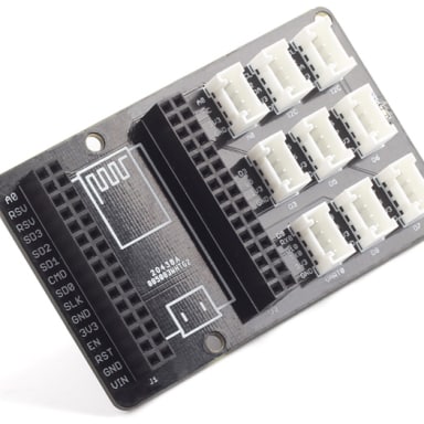
If your project is space limited, here is a Serial CAN-BUS module which has the full features of CAN Bus. The Serial CAN-BUS provides your Arduino or others MCU with the capability to communication to CAN Bus, such as hacking your vehicle. This Grove CAN-BUS module is controled by UART, that means if your MCU has a UART interface, this serial CAN BUS is available. Good news is that this Serial CAN BUS module needs only $14.9

What’s new in CAN BUS Shield V1.2
Pads on the backside of PCBA
Change terminal resistor to 120 Ohm
Note
CAN BUS Shield Work well with Arduino UNO (ATmega328), Arduino Mega (ATmega1280/2560) as well as Arduino Leonardo (ATmega32U4) and LinkIt One, if you want to use it with the others board, please contact us for more details.
| Arduino UNO | Arduino Mega | Arduino Leonardo | |
| CAN-Bus Shield V1.2 | Compatible | Compatible | Compatible |
If you want a CAN Bus function for others mcu, please try Serial CAN-BUS module.
Features
Implements CAN V2.0B at up to 1 Mb/s
Changeable chip select pin
Screw terminal that easily to connect CAN_H and CAN_L
Arduino Uno pin headers
2 Grove connectors (I2C and UART)
SPI Interface up to 10 MHz
Standard (11 bit) and extended (29 bit) data and remote frames
Two receive buffers with prioritized message storage
Industrial standard 9 pin sub-D connector
Two LED indicators
Technical Details
| Dimensions | 72mm x 54mm x 27mm |
| Weight | G.W 49g |
| Battery | Exclude |
Part List
| CAN-Bus Shield V1.2 | 1 |
Learn
[Wiki]CAN-BUS Shield V1.2
This CAN-BUS Shield adopts MCP2515 CAN Bus controller with SPI interface and MCP2551 CAN transceiver to give your Arduino/Seeeduino CAN-BUS capability. With an OBD-II converter cable added on and the OBD-II library imported, you are ready to build an onbo

Volkswagen CAN BUS Gaming
Ever wanted to play a car/truck simulator with a real dashboard on your PC? Me too! I'm trying to control a VW Polo 6R dashboard via CAN Bus with an Arduino Uno and a Seeed CAN Bus Shield. Inspired by Silas Parker. Thanks to Sepp and Is0-Mick for thei